# The BrainBox
The BrainBox is the center of the kit, it controls power, provides you with useful electronics and is where your code runs. Do NOT open the BrainBox unless given written permission by Hills Road RoboCon.
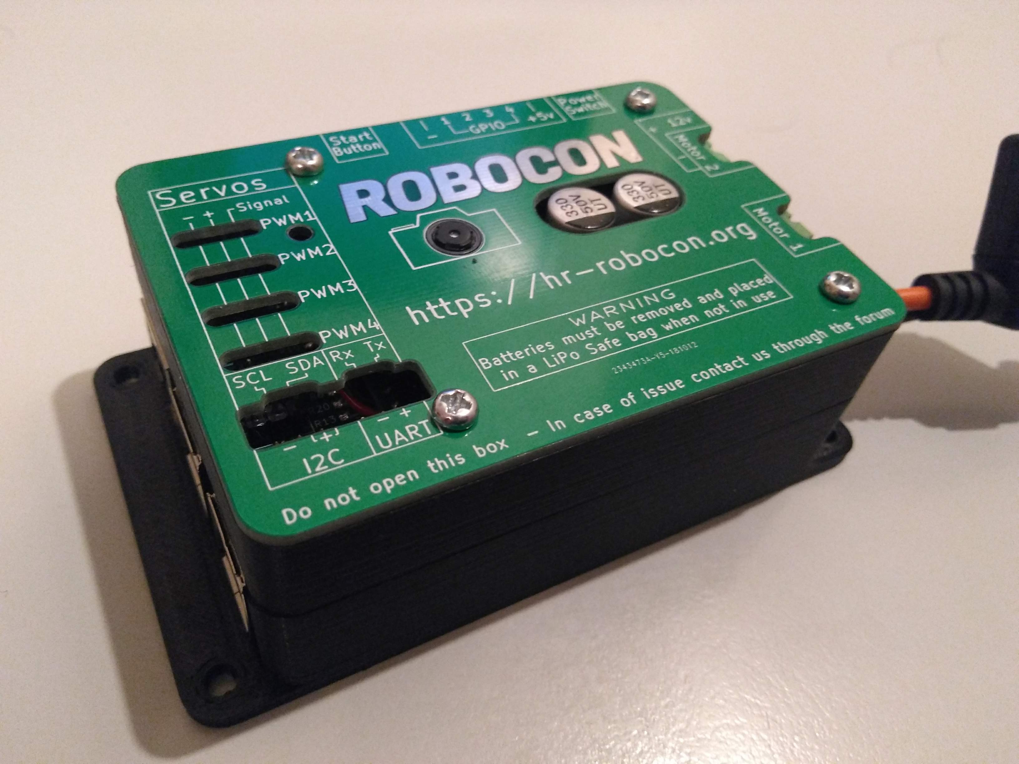
# Power
The BrainBox distributes power to the robot from the battery. It provides both 12V and 5V power out. All power must go through the BrainBox and the fuse should never be replaced.
The On|Off switch also plugs into the BrainBox as well as the Start button which is used to start your robot code running.
# In order to attach a battery to the BrainBox:
- Make sure it is disconnected from its charger.
- Plug the yellow (XT60) connector into the corresponding socket on the brainbox (the socket should also be yellow)
Powering on the BrainBox:
- Find your provided power switch.
- Plug the black connector end into the black socket labelled “Power Switch” on the BrainBox. (See diagram for details)
- Press the power switch button. The status indicators on the battery should turn on.
- Wait for these to stop flashing. Your BrainBox is now powered on!
# Connecting to the BrainBox and setting up code:
Now that the brainbox is powered on, turn on your laptop and open the User account.
Open the Wi-Fi menu. You should see a network called “RoboCon[Current Year]-Team[Team No.]”, for example, RoboCon1234-Team1 The team number should match the number on the laptop.
Select this network. When prompted for a password, enter the one found on the bottom of the BrainBox.
Navigate to the web address found on the BrainBox.
You should be given options for Rules, Editor, Docs, and Run. a. Rules will contain a copy of the competition’s rules. b. Editor will allow you access to the code on the robot. c. Docs will contain the documentation for the code. d. Run will run the currently loaded .py script on the robot.
Navigate to the Editor window. It should look as below.

# Motors & 12V Power
The specifications for the motor board can be found here, however to summarize:
| Condition per channel | Maximum Value |
|---|---|
| Continuous current | 10A |
| Peak current (10 seconds) | 30A |
| Operating Voltage | 12V |
TIP
You can toggle the 12V which allows you to turn 12V devices on and off easily. However, this will also cut power to the motor board.
# GPIO
# GPIO - Out
All of the BrainBox's GPIO pins are connected in-series with a 1K Ohm resistor, to provide current limiting. This means that you can plug devices such as LED's straight into your BrainBox.
Nominally they operate at 5V but depending on your load the true output will vary. You can calculate the voltage you will get across your load by measuring its resistance, then doing the sum:
(5*Load_resistance)/(Load_resistance+1000)
# GPIO - In
We advise against you using analogue inputs with an impedance (You can think of impedance as "effective resistance in an analogue circuit") of greater than 9K Ohm's as this will result in values which do not necessarily correspond to what you'd expect.
If you need to sense something with an impedance of more than 9K then you will need to use an Op-amp to buffer the input. If you would like more details on how to do this please contact us on the forums.
# GPIO - Limits
Do not try and sink or source more than 25mA into the BrainBox's GPIO, it may damage some of the internal components.
# PWM Pins
PWM (Pulse Width Modulation) is a technique used for sending signals to a device for how much it should do a thing. This could be how fast to spin a motor, or the position to turn an RC Servo to. It does this by sending regular pulses, which vary in width. The length of the pulse tells the device how much to do the thing. If you are interested you can find out more about using PWM for control here.
Please note you will not be able to drive large motors over the PWM pin's supplied as the maximum which they can supply is 3A at 5V.
The PWM pins ranges:
| Value | Pulse |
|---|---|
| 0 | 1.5ms |
| 100 | 2ms |
| -100 | 1ms |
| 178 | 2.39ms |
| -178 | 0.61ms |
# Pin Out
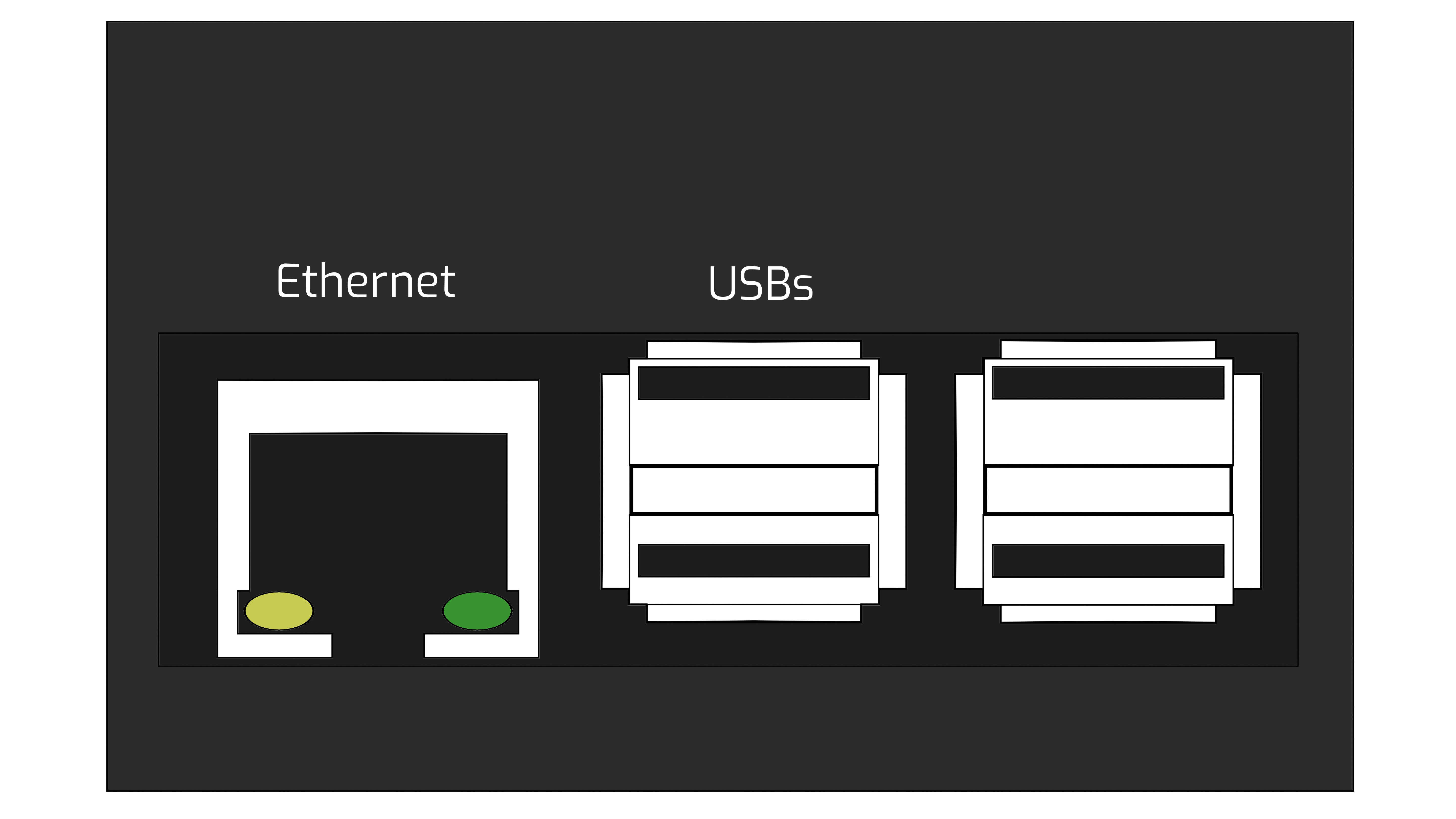
# USB's
# Motors

# GPIO
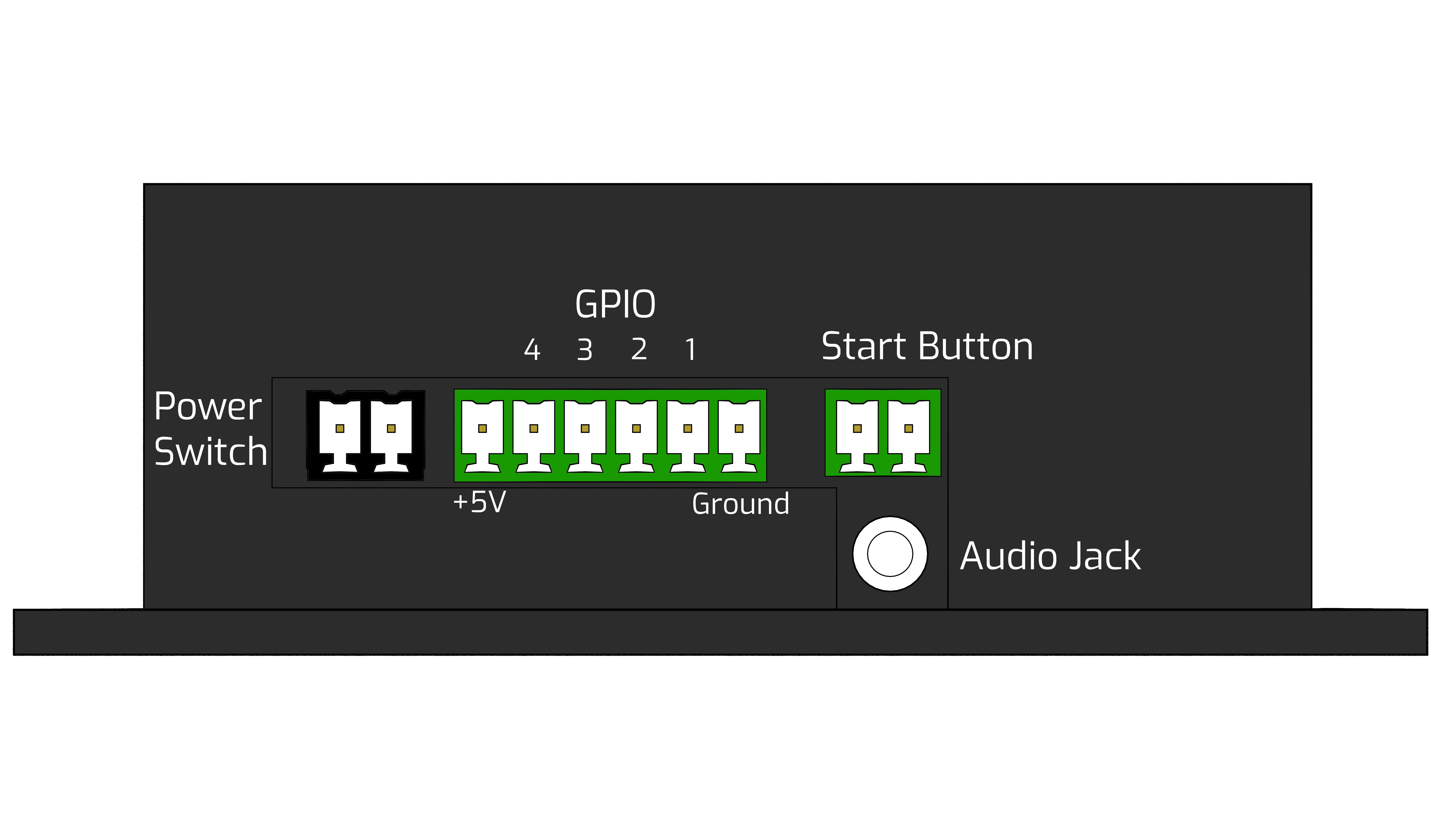
# Front
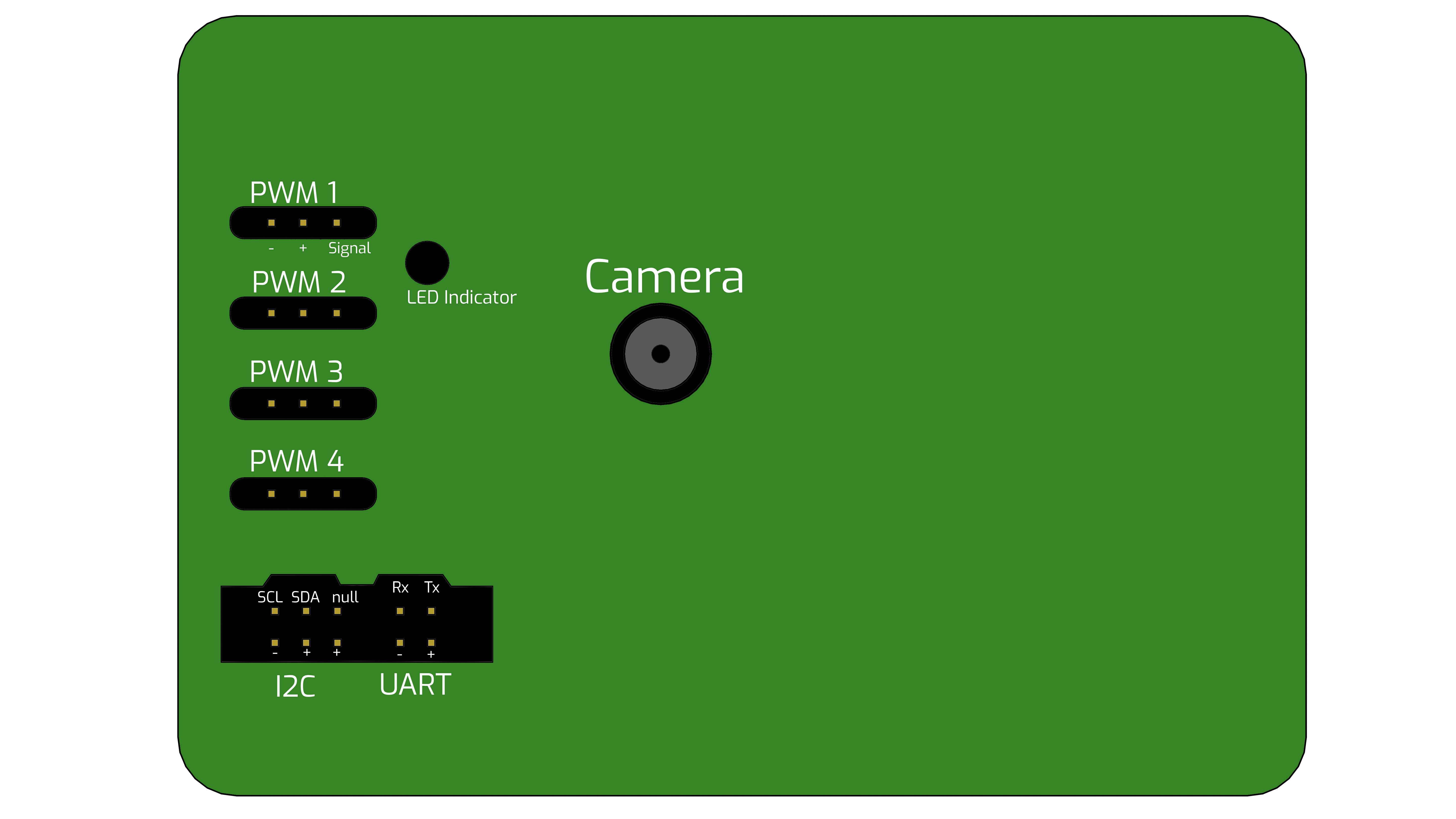
# Expansion I2C, UART & USB
For expansion please see the expansion page.
# Minibot Assembly
You can download instructions on how to make your minibot here.